안녕하세요. 마이케이블입니다.
미국 스위치크래프트 고급XLR(숫)단자를 소개합니다.
메탈통바디 단자로 단자 뒷면은 고무재질로 되어있습니다. 핀은 금도금 처리되어 신호전도율과 고급스러움을 더했습니다.

A SERIES - REMOVABLE INSERT, STANDARD CABLE CLAMP
QGP SERIES - NON-REFLECTIVE FINISH, REMOVABLE INSERT, STANDARD CABLE CLAMP
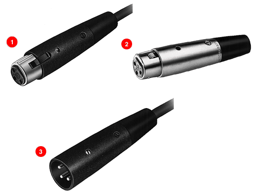
1. A(*)F CORD PLUG
2. A(*)FD CORD PLUG
3. A(*)M CORD PLUG
4. QGP CORD PLUG
Click above to download drawings (you will need to have Adobe Acrobat installed on your system to do this).

A(*)F CORD PLUG
Straight female cord plug with standard latchlock. Available in 3-7 pin versions.
A(*)FD CORD PLUG
Straight female cord plug with FAS-DIS-CONNECT detent.
A(*)M CORD PLUG
Straight male cord plug.
QGP CORD PLUG
Shell: Die-cast zinc, non-reflective gray Vel-Tone® finish.
Socket Contacts: Gold-plated copper alloy
Pin Contact: Gold-plated copper alloy
*Number of insert contacts or pins must be specified to complete part number.
PART NUMBERS - FEMALE CORD PLUGS
| Standard Q-G® Cord Plugs, Series A(*)F and QGP |
| Satin Nickel Finish |
Black Finish |
Fas-
Dis-
Connect |
Large Flex Relief2 |
QGP Series |
Insert Contacts |
| Silver1 |
Gold1 |
| A3F |
A3FB |
A3FBAU |
¤A3FD |
A3FL |
QGP322 |
3 |
| A3FS3 |
- |
- |
- |
- |
- |
3 |
| A4F |
A4FB |
A4FBAU |
¤A4FD |
A4FL |
- |
4 |
| A5F |
A5FB |
A5FBAU |
¤A5FD |
¤A5FL |
- |
5 |
| A6F |
A6FB |
A6FBAU |
- |
- |
- |
6 |
| A7F |
A7FB |
A7FBAU |
- |
- |
- |
7 |
1 Contact plating.
2 Accepts cables from .25 inch (6.35 mm) to .328 inch (8.33 mm) diameter
3 Accepts cables from .105 inch (2.7 mm) to .205 inch (5.2 mm)
¤Available on special order only; contact Switchcraft for price and delivery.
PART NUMBERS - MALE CORD PLUGS
| Standard Q-G® Cord Plugs, Series A(*)F and QGP |
| Satin Nickel Finish |
Black Finish |
Large Flex Relief |
QGP Series |
Insert Contacts |
| Silver |
Gold |
| A3M |
A3MB |
A3MBAU |
A3ML |
QGP323 |
3 |
| A3MS3 |
- |
- |
- |
- |
3 |
| A4M |
A4MB |
A4MBAU |
A4ML |
- |
4 |
| A5M |
A5MB |
A5MBAU |
¤A5ML |
- |
5 |
| A6M |
- |
A6MBAU |
- |
- |
6 |
| A7M |
- |
A7MBAU |
- |
- |
7 |
All above part numbers have black flex relief installed. Contact Switchcraft for color flex relief.
¤Available on special order only; contact Switchcraft for price and delivery.
Q-G® CONNECTORS
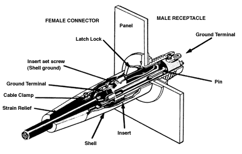
SECTIONALIZED VIEW - A3F Plug to B3M Receptacle

DESIGN FEATURES
CONSTRUCTION: Sturdy, die-cast zinc with satin nickel finish or Black-Velvet® finish to withstand hard use - even abuse. Vel-Tone non-reflective finish on QGP (XLR) connectors only.
INSERT INSULATION: High-impact, molded thermoplastic provides high dielectric strength, and superior insulation resistance.
LOCKING: Latchlock on female plugs and receptacles locks into groove in mating male connector to prevent accidental disconnect. Manual release of latchlock is required to separate connectors. Q-G connectors are also available with FAS-DISCONNECT detent in place of latchlock. QGP (XLR) has die-cast latchlock.
FAS-DISCONNECT: FAS-DISCONNECT detent permits immediate disconnect of locked connectors with a 4-pound (1.8 kg) force. FAS-DISCONNECT connectors are not recommended for use in situations where strong or violent pulls on cable may occur and cause accidental disconnect. Available on Q-G (XLR) connectors only.
DUAL PRESSURE PLATES: A*F and A*M Series provides secure cable lock and strain relief for all standard size cables.
FLEX RELIEF: TPR cable flex relief bushings on cord plugs are keyed to shell. Standard bushing opening accepts cables from .21 to .3 inch diameter Bushings with other openings accommodate cables from .105 to .205 inch diameter and from .3 to .328 inch diameter.
CONTACTS: Q-G female connectors are copper alloy, silver-plated, tarnish-resistant; male contacts are copper alloy, silver-plated, tarnish-resistant. Gold-plated female contacts are copper alloy. Male contacts are gold-plated.
WIRING: Large, unique design solder cups make wiring fast and easy. Certain receptacles are also available with PC terminals for use with printed circuit boards.
Grounding and Shielding
Tightening the insert screw establishes continuity between ground terminal, ground contactors and connector housing. Upon engagement with a mating plug or receptacle, the ground circuit is automatically connected to the mating shell through the ground contactor. Any pin or contact can be grounded by "jumping" it to the ground terminal. Contact 1 engages before all other contacts and disengages after all other contacts.
Field-proven Switchcraft Q-G (XLR) ® (Quick-Ground) 3- through 7-contact audio connectors with ground terminal and ground contactors are available in a wide range of plugs and receptacles for microphones, test equipment, instrumentation, computers, video cameras, mixing consoles, tape recorders, PA and sound reinforcement, stereo systems and many more applications.
Switchcraft Q-G (XLR)® connectors feature a separate ground-terminal electrically integral with connector shell. Ground continuity between mating plugs is automatically accomplished through exclusive "Dual Point" grounding system. Socket and pin assemblies utilize "wedge-action" to insure firm, reliable positioning in connector shell. Inserts are easily removable for wiring and soldering. High-impact thermoplastic insures long reliable insert assembly life. Female connectors have latch lock feature to hold connectors firmly together. Plugs and receptacles are mechanically keyed for proper mating. Q-G (*) Series 3-, 4-, 5-, 6-, and 7-pin/contact connectors offer 4-, 5-, 6-, 7-, and 8-pin contact versatility when ground-terminal is used. Switchcraft QGP connectors; are compatible with 3- and 4-contact (Neutrik, Amphenol 91-850 and Excellite 91-450 Series, and Cannon XLR-3, XLR-4): 5-contact (Neutrik, Cannon XLR-5 and Amphenol Excellite 91-450 Series).
Captive Design®Insert Screws

Insert screw engages as any conventional screw, except it is lefthand threaded. To disassemble the connector, turn screw counterclockwise down into insert (see illustration).

Insert assembly is now readily removed from shell. Note "Ground Terminal" area - large soldering cups make cable installation fast and easy. Unitized 1-piece insert eliminates possible loss of latchlock and spring.

To reassemble, replace insert assembly into shell, align insert screw under hole in shell and secure insert by turning insert screw clockwise. This "wedges" insert against interior of shell providing a rigid connector assembly and positive electrical continuity between ground terminal and shell (see illustration).